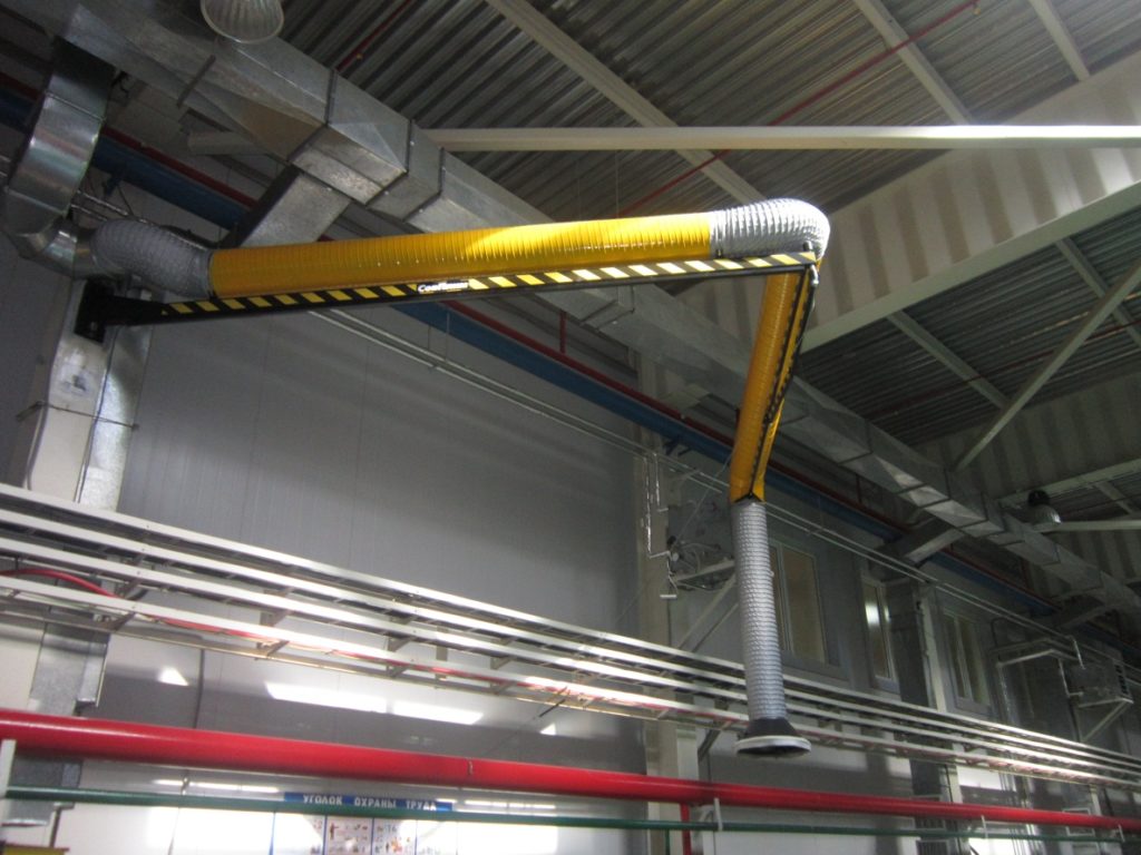
The device is a cantilever swivel beam, at the free end of which exhaust funnel is present. The exhaust gases are removed by an exhaust fan through a flexible hose and air duct.
Benefits
• Preservation of personnel health (protection from harmful exhaust gases);
• Low power consumption by reducing the load on general ventilation;
• Efficiency and high productivity;
• Flexibility and large radius of action;
• Simple installation and operation (managed by 1–2 depot employees);
• Reliability and long service life.
Working conditions
The device is designed for continuous operation in a closed workshop under the following conditions:
• ambient temperature from +5 to +45 °С;
• relative humidity not more than 80% at +25 °С;
• the temperature of the transported air-flow should not exceed +400 °С.
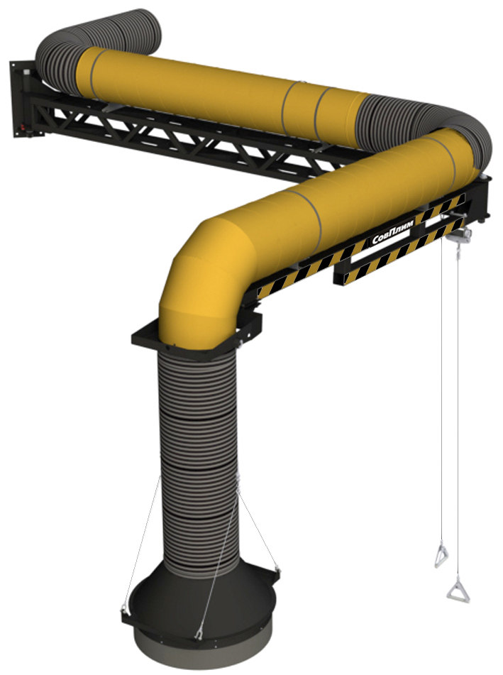
Overall view and main components of the device.
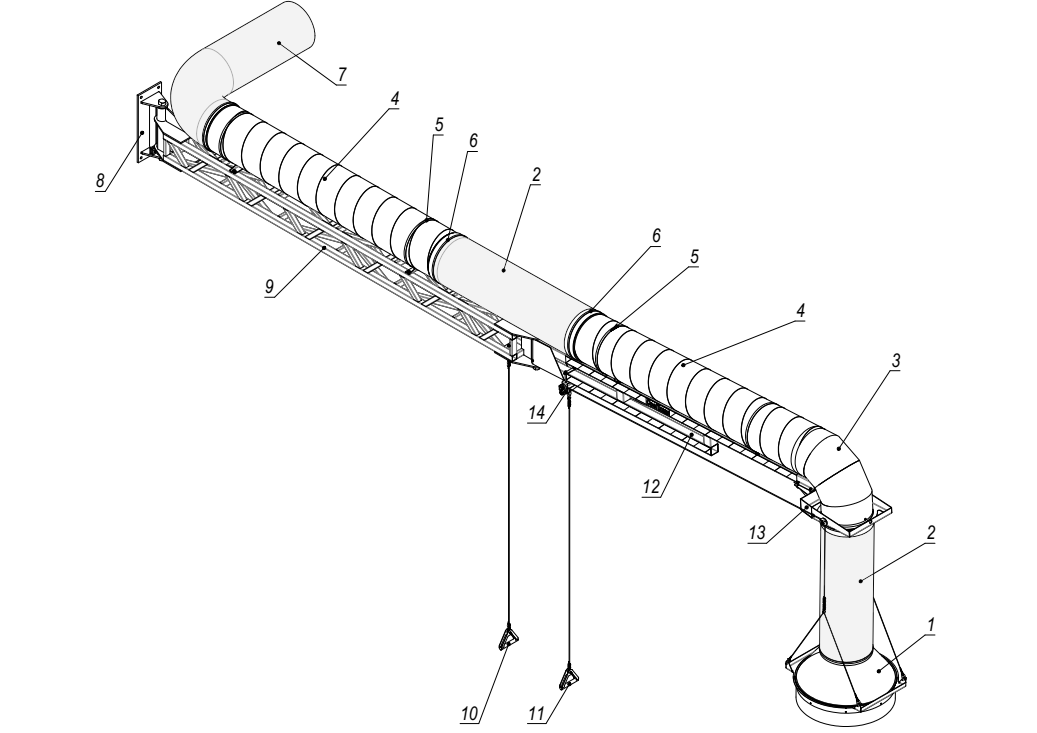
1 – Intake funnel;
2 – Flexible hose L=1.2m;
3 – Bend angled 90°;
4 – Air duct;
5 – Worm clamp;
6 – Spiral clamp;
7 – Flexible hose L = 1.5m;
8 – Mounting frame;
9 – Internal beam;
10 – Control cable;
11 – Funnel lifting rope;
12 – External beam;
13 – Support bracket;
14 – Traverse
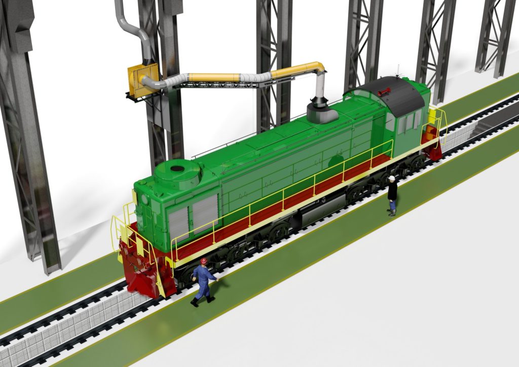
At the locomotive maintenance point at a certain point on the railway track, a movable console is installed, which is attached to a vertical surface (wall, column) using an assembly platform (8).
The console consists of two beams (arms) (9, 12), which can be rotated about ±90° relative to the platform and 180° relative to each other.
• The swing control of the console beams is carried out using steel cables (10, 11).
• Adjustment of the force of turning the beams is carried out by pressing the brake pads with screws, preventing their involuntary “departure” from the place of work.
When the locomotive stops in the coverage area of the system, a funnel Ф600mm is brought to its exhaust pipe (1).
Ring magnets (4 pcs.) Are installed inside the funnel, which makes it possible to reliably fix the funnel to the surface of the locomotive’s roof, thereby practically eliminating the emission of polluted air into the atmosphere of the maintenance point.
From the funnel comes a heat-resistant hose (2) connected to the air duct (4). The air duct runs along the console and is attached to it along the upper edge with clamps (5,6).
A stand-alone fan, connected to the UKL exhaust unit, removes exhaust gases from the exhaust line through a heat-resistant hose and air duct outside the room.
Design changes are possible in accordance with specific customer requirements (length of beams; diameter of air ducts; diameter of an exhaust funnel; temperature resistance of hoses)
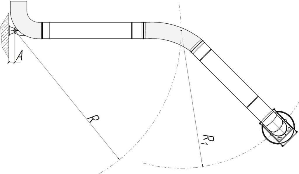
Working area radius
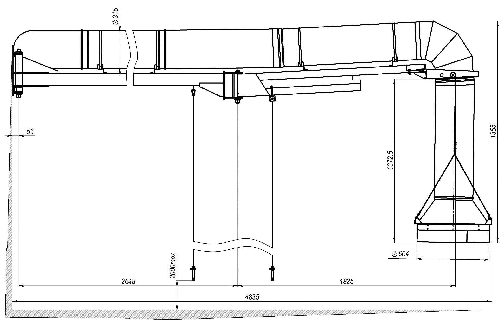
Overall Dimensions for UKL-4.5
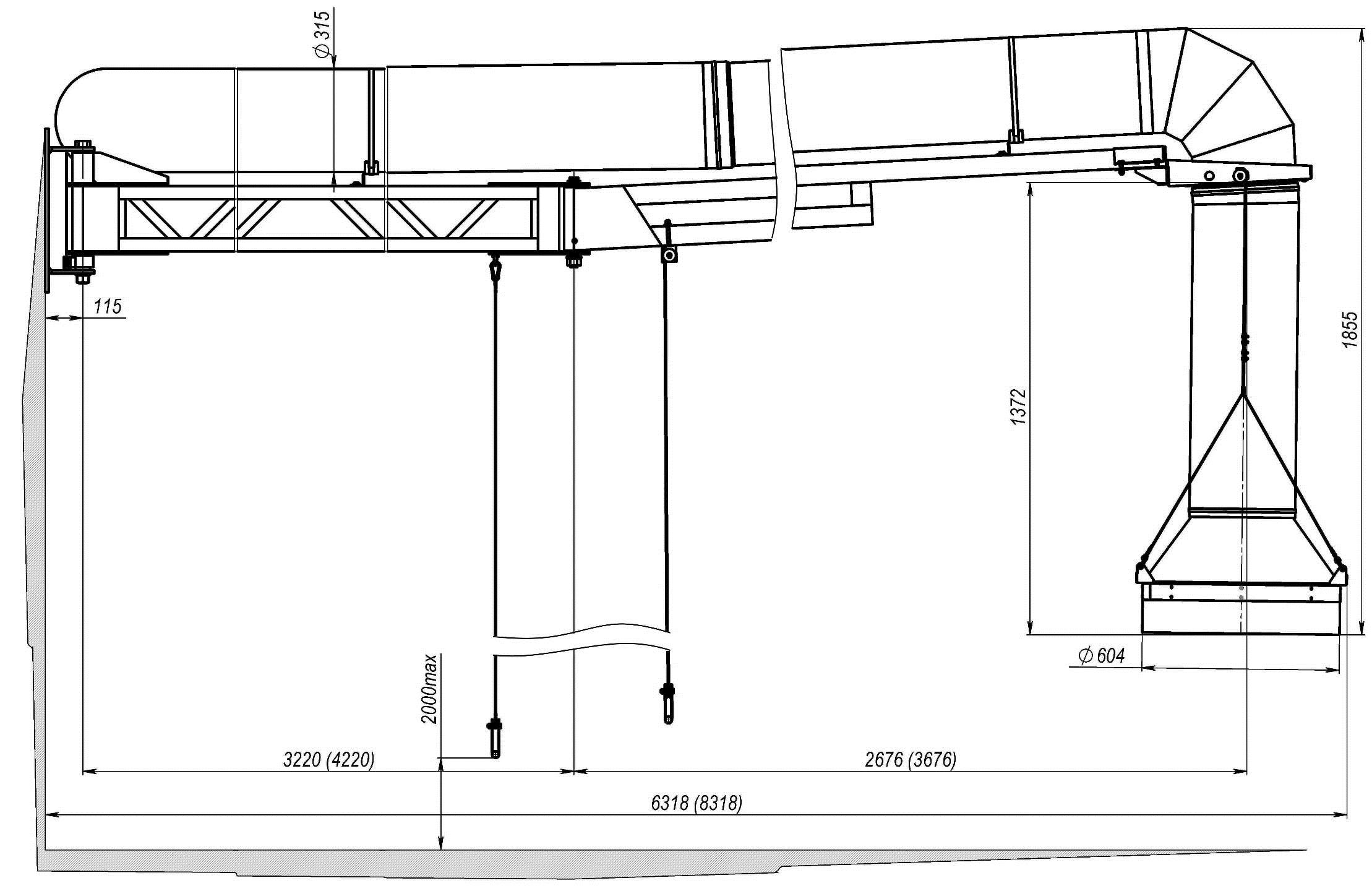
Overall Dimensions for UKL-6 and UKL-8
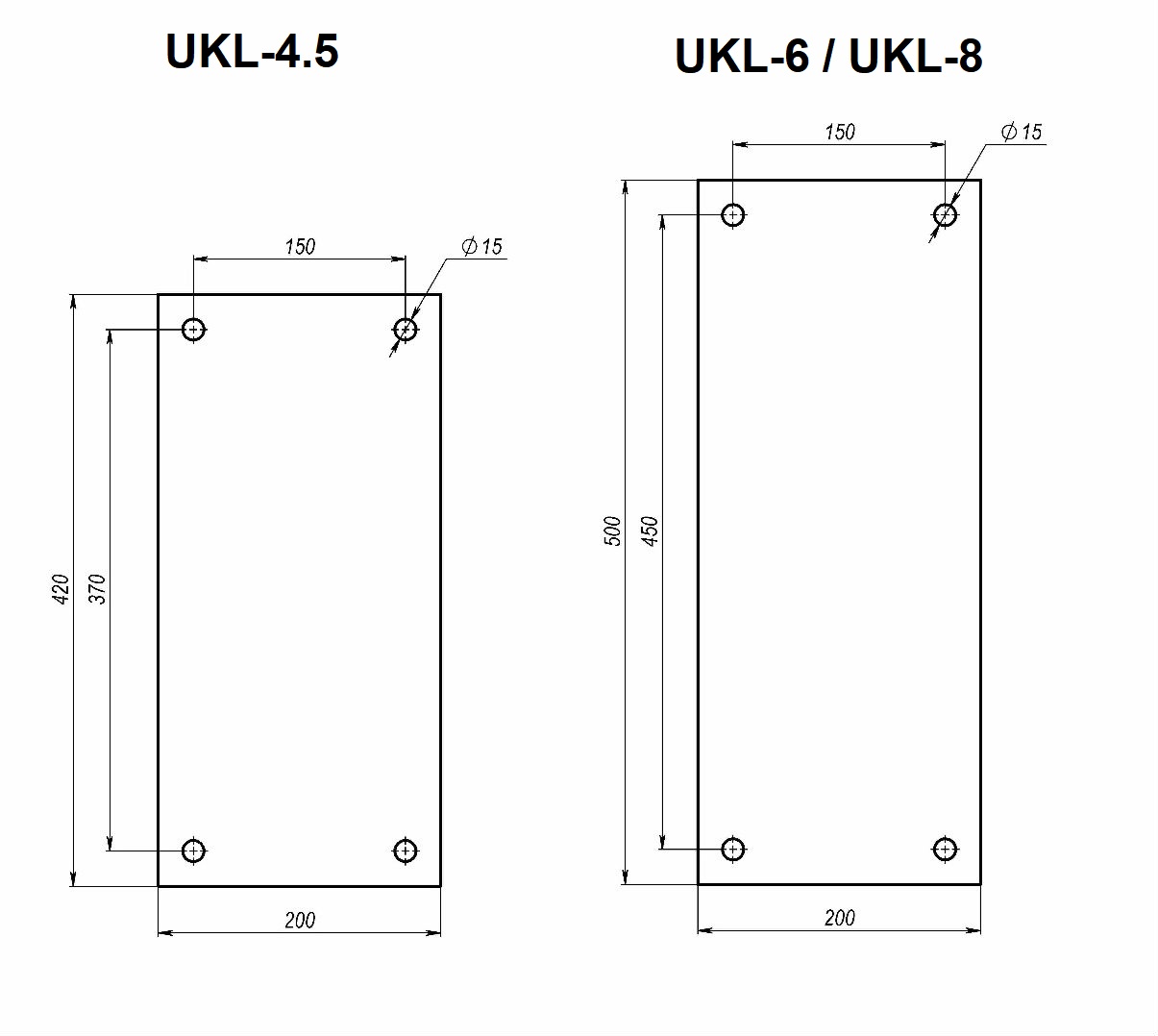
Mounting Specifications
[table “282” not found /]
Overall dimensions of mounting frame